Use a stud finder to ensure there are no obstructions such as studs, wires, pipes, etc., within the wall. The wall thickness must fall between 3 4/5″ to 7 4/5″.
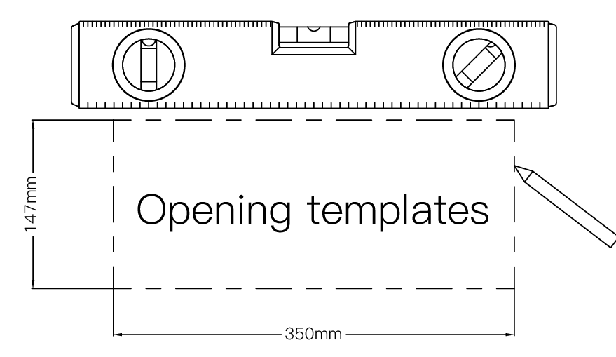
2) With a leveling tool, ensure the device is well positioned horizontally and vertically. Mark a precise locating point. Retrieve the opening template provided with our product (do not discard it after use, as it will be needed in subsequent steps). Use it to trace the corresponding line.
Step 2:
Using a plasterboard saw, carefully cut along the line drawn
in Step 1. For a smoother cut, it’s recommended to use a level to ensure accuracy. Remember to prioritize safety throughout the cutting process. Once the hole is cut, remove the outer baffle and compare it.
Step 3:
Using a screwdriver or sharp object, puncture the opposite gypsum board at the two corners of the cut. It’s recommended to carefully compare the cuts in Figure 2 to maintain uniformity during this step. Next, retrieve the opening template used in Step 1 and trace lines for cutting. Before cutting each edge, remove the outer baffle for comparison. Repeat Step 1 and Step 2 as necessary.
Step 4:
After completing the opening step, unscrew the removable iron tabs
located either at the top or bottom of the product, depending on your
wiring setup (you may choose to remove either the top or bottom tabs).
Install the clip-on cable retainer onto the product, ensuring you observe the correct direction of installation. The clip-on cable retainer should be provided with its own specifications, including size: 3/8 .
Step 5:
Before proceeding with this step, ensure that the circuit to be installed
is de-energized!
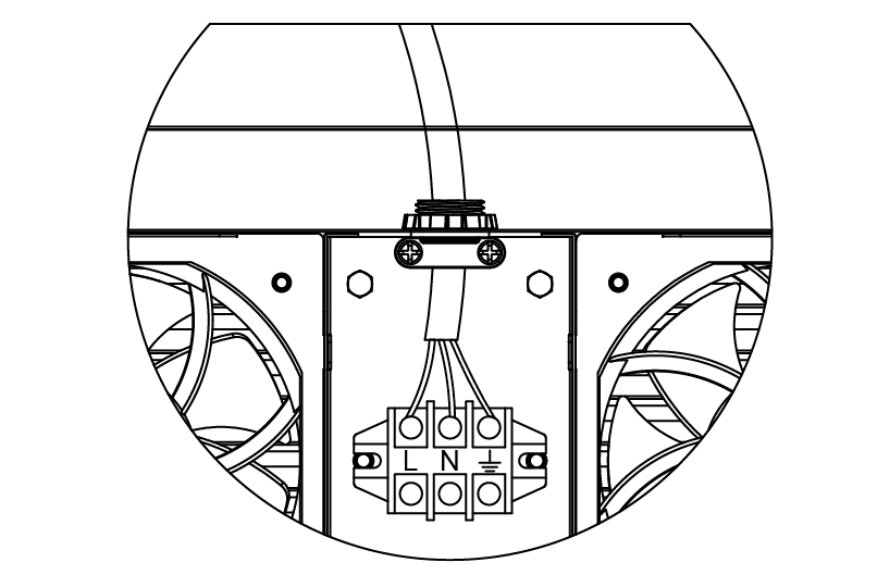
Guide the power cord into the clip-on cable retainer on the product.
Following the circuit diagram, connect the power cord’s live, neutral, and ground wires to the product’s wiring plug in the specified order, taking care not to miss any copper strands, as this could result in power leak age. Finally, tighten the screws on the clip-on cable retainer to secure the power cord.
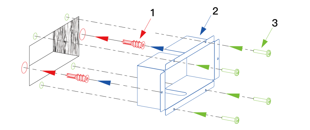
Step 6:
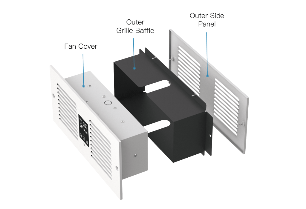
Begin by removing the outer baffle from the product and installing it. First, align the drywall rivets located in the red section of the picture with the corresponding holes in the gypsum board, then drive them in. Next, install the outer baffle into the blue section accordingly. Finally, secure the outer baffle by driving the self-tapping screws located in the green section into the holes of the outer baffle.
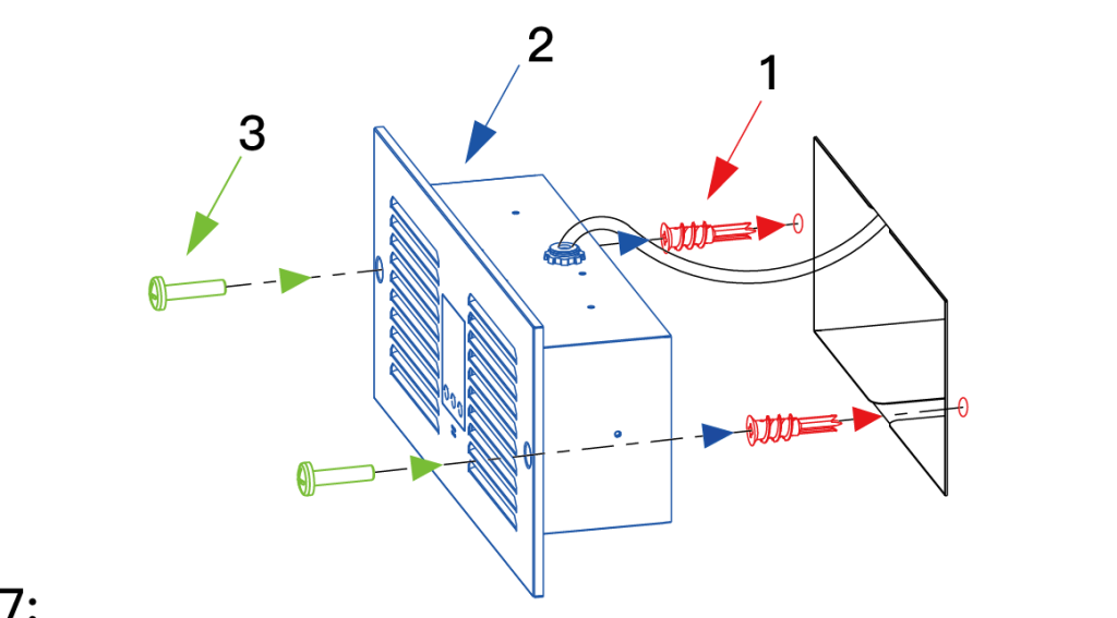
Step 7:
After installing the outer baffle, proceed to install the fan part of the
product into the outer baffle, ensuring levelness. Begin by installing the drywall rivets into the designated holes (red), then insert the fan part (blue) Finally, secure it in place with screws (green).
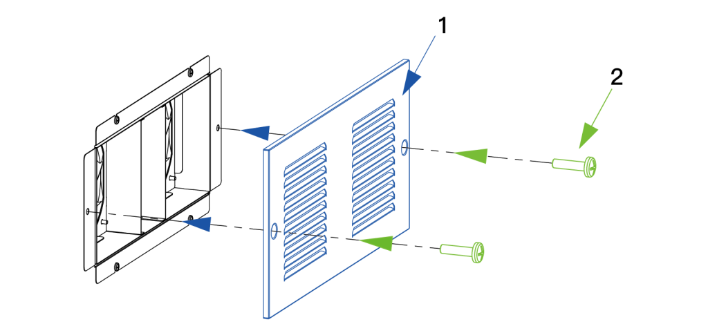
Step 8:
The final step is to install the air guide panel. Align the air guide panel
(blue) with the corresponding holes, then secure it in place using screws (green). Once this is done, the installation is complete.